Sunday 31 December 2023

I can see the attraction!

"Next (and last) unimplemented mode (as defined by the MD bits) is the 2-plane 8-bit (pattern name) mode which is used by the games themselves. That shouldn't be too difficult to implement (or more correctly, fix) but it does take a while for the simulation to get that far."

Famous last words! It has taken a few re-writes of a good chunk of the logic in the pattern generator, but I'm finally seeing at least Xevious and Mappy running in attract mode! Not much to see of Galaga except a few words on the screen, but that could be palette issues.

The aforementioned mode also requires both the page table and base address registers to be implemented and included in the pattern generator calculations. Not overly complex but a number of different combinations to account for in shifting values around relative to one another. It does pay to read - and re-read - the documentation as much of the logic that I ended up re-writing was summarised quite nicely in a few tables in the YGV608 Application Manual.

Anyway, here's some eye candy from the attract mode:

Xevious original and Arrangement versions (simulation)

Mappy original and Arrangement versions (simulation)

Not every mode is fully implemented yet either; only 8x8 & 16x16 tiles, and it assumes only Page 0 is in use on each plane. I will have to look at scrolling soon too!

One issue I have is that I currently have only a fraction of the graphics ROM loaded into the real MiSTer project, as it is residing in on-chip RAM. So I can only test that the correct tiles are being displayed under simulation. And under simulation, it takes 81 mins to get to the original Xevious attract mode, and a tad over 2hrs to get to the original Mappy attract mode!

Now that I've gotten this far, it's time to get the graphics ROM loaded into SDRAM. I have the option of using the 2nd SDRAM module on my development MiSTer, but haven't decided if that's necessary just yet...

Wednesday 27 December 2023

Bigger tiles!

Almost impossible to find the time to work on Namco Classics but managed to find a few minutes here and there. After a false start I've updated the core to handle tile sizes other than 8x8 (16x16, 32x32 & 64x64) which is used on the game select screen.

16x16-pixel tile mode (MiSTer)

The dual-plane is also working as can be seen on the per-game select screen.

Next (and last) unimplemented mode (as defined by the MD bits) is the 2-plane 8-bit (pattern name) mode which is used by the games themselves. That shouldn't be too difficult to implement (or more correctly, fix) but it does take a while for the simulation to get that far.

Tuesday 26 December 2023

Xmas progress!

Not surprisingly it's been a busy run-in to Xmas with work and home life, though I have done more on Namco Classics than my lack of blog posts would suggest. In fact, I've been quite pleased with my progress given the relative lack of time to work on it.

To continue where the last post left off, I've sorted the interrupt issue. That was due to me not responding with VPAn properly - interestingly that signal was absent on the TG68K core I used many years ago for the beginnings of my Neo Geo implementation. The software seems to be running properly now as far as I can ascertain from the far-from-complete video implementation.

Next step was to get the fx68k core executing code from SDRAM. That involved studying a bunch of different cores to find an SDRAM controller that was relatively 'new' and also suited my circumstances. Turns out the core written by Sorgelig is used in several different cores, and modified as required. After a false start using the Irem92 version of the core (see below), I finally settled on the version used in the SEGA Genesis core. FTR it has 3 channels, though I'm only using 1 atm.

Before I can use the SDRAM core however, I need to be able to download to the SDRAM. For this I found the Irem92 rom_loader module, which uses some magic in the .mra file to download data to both SDRAM and BRAM memory blocks. This was perfect for Namco Classics as I am still loading a subset of the graphics ROM into BRAM, although I soon discovered that I'd need to switch the SDRAM core to that of the Genesis core. Fortunately the rom_loader didn't require any changes.

Finally I was greeted with the SELF TEST screen that I had only seen on the simulator...

68K code running from SDRAM!

I decided to look at the dipswitches next, so I could get the game into the self-test menu. Quite straightforward with the MiSTer framework, so then I started looking at the inputs to the core. This was a little more confusing as the documentation is quite terse on this topic, and took some 'reverse-engineering' of another core to deduce how that actually works. Eventually I could navigate the menu and get into the SWITCH TEST screen.

SELF TEST (inputs) screen (MiSTer)

That just about completes the interfacing with the MiSTer framework, at least until I want to get more into the advanced graphics and sound options.

So back to completing the YGV608 implementation. It doesn't take long for the game to switch into an unimplemented graphics mode. The main title screen runs in 256-colour mode, so that was next. At the end of the day, all that was required was a few more lines of Verilog in the Pattern Generator module and it was displaying correctly!

Title screen - 256 colour mode (MiSTer)

And then the very next screen in attract mode switches to another unimplemented graphics mode... this time 16x16-pixel tiles instead of 8x8-pixel tiles. This is currently WIP, but I at least now see something resembling the proper graphics:

16x16-pixel tile mode (Verilator)

So far the new graphics modes have been trivial to implement, but I'm expecting it to get more complex before too long. Scrolling and paging in particular, and that's not even thinking about rotating and scaling (which the NAMCO intro screen uses!) But soon it may be time to implement the sprite layer!

Friday 8 December 2023

Is your RAM OK?

Another very productive day!

I started out trying to get the code a bit further to display more on the screen. I was frustrated by the inefficient process of tracing execution via the waveforms in gtkwave. I had already written a crude "breakpoint" mechanism that simply halted the execution at that point, but it required re-compiling the simulation to change the address. So next task was to implement something more convenient.

After undergoing a baptism by fire with ImGui I ended up with some GUI elements allowing me to type in a breakpoint address, display the current address on the bus (PC), and the data bus values. I also added a button to go to the next address that was doing an instruction fetch (it was too complex for now to work out how to step to the next actual instruction - I was in a hurry).

CPU 'debugger' in the Verilog simulator

Now back to tracing the program and working out where it was spinning. Again, going back to my original MAME driver to look at the H8/3002 hacks, I implemented the very crude CUSKEY hack that ultimately allowed the RAM test to PASS. Then it was more RE in IDAPro trying to get it to jump to the full SELF TEST menu screen - to no avail. 1MB of code is a *lot* to search through!!!

Eventually I found it was spinning on a RAM address, waiting for the value to change. It appears that value is being changed in one of the ISR's. I had written the code to generate the VBLANK interrupt from the YGV608 and hook it up to the 68K core, but I hadn't seen it actually working. So I hooked it up again and all hell broke loose. I'm yet to confirm but it appears that as soon as interrupts are enabled in the core, it tries to service the pending VBLANK and fetches the INITIAL STACK POINTER vector and jumps there... have to look further into it as I'm no 68K hardware expert.

Changing tack for the day I decided to clean up the YGV608 Pattern Generator (tile display engine), re-writing it to support all 4 pattern plane modes and various page sizes. That required work on the register side that writes the pattern name table RAM, and the pattern generator itself. But as I knew it would, the logic shrinks down when you optimise it properly, though I have opted at this stage to tend to keep it readable. Finally I could see 'RAM OK' instead of a bunch of zeroes.

Last task was to account for the pipeline delays in the pattern generator and color bus to fix the clipping of characters. After hand-drawing a timing diagram in my 'retro project' notebook, it was obvious where I had to pipeline some counters, and only two compiles to get it right!

The first really clean display - simulation output

So a fairly clean display. I haven't accounted for the pipeline delays between the border and the pattern planes yet, hence the extra lines either side of the border. I should also note that I've only really just scraped the surface of the YGV608 functionality thus far, even where the pattern planes are concerned. There's the virtual screen made of (repeating) pages of planes, flipping, reversing, scrolling regions, transparency, mosaic displays, display priorities, name table mapping modes.... not to mention sprites and rotation! Having said that, I didn't even implement every function in the MAME driver either!

So next... I think I'll have to get interrupts working to get much further in executing the code. No point implementing YGV608 features that can't be tested!

Wednesday 6 December 2023

"ND-1 SELF TEST / VER1.00"

Continuing on from where I left off yesterday, I've implemented the color (sic) palette interface and memory, and also got the code to the point where it displays text on the screen!

It hasn't been without some head-scratching and some 'doh' moments though.

A combination of quick hacks, some unfounded assumptions, and confusion over how the YGV608 was wired to the 68K data bus resulted in some copious head-scratching. I decided that it is wired to the upper [15:8] bits on the bus, but then I observed the 'clear screen' function writing alternate '$20' and '$00' to the pattern name table. Confused by the fact that $20 was always either on the upper or lower half of the bus, and the fact that the code was alternating between byte and word access to the YGV608, I thought I'd have to decode UDSn and LDSn to get the right half... and then I eventually realised that the YGV60 was in 16-bit pattern mode and it should be writing those two bytes!

Next was getting the execution to a point where it was actually writing something to the pattern name table (displaying characters on the screen). On a cold boot it shows the self-test screen, but before it gets there it checks a few things that aren't implemented, one of which is communications from the H8/3002 via shared RAM.

Now way back when I wrote the MAME driver, I was pretty sure there was no H8/3002 core and that I had done a very crude 'black box' emulation of the MCU functionality. I just had to find it. Fortunately mamedev keep archives of all their old releases, and using a 'binary chop' I found a release (0.53) with what is likely my original driver. And sure enough, there was the hack for the missing MCU!

I traced the execution of the simulation where it was spinning, waiting on a shared memory location, and implemented the hack for that address. Running again it got further, showing a few lines of '0000' on the otherwise clear display. My guess was that the pattern generator was picking up the wrong byte in my quickly-hacked 16-bit pattern mode - and I was right. After I fixed that, I got this:

NCV1 running under simulation - text output

Nowhere near perfect but good enough to verify the CPU is executing and displaying text via the YGV608. And FTR, the '0000000' string should actually be 'RAM NG', but it's still picking up the wrong byte on that line. It took me a minute to realise why the RAM test was failing when I'd implemented all of it - because of the shared-RAM hack I implemented!

Anyway very good progress today but it's probably a good time now to step back and actually implement the pattern generator properly, to handle all modes. It was originally a quick hack for 8-bit mode (only), then re-hacked for 16-bit mode (only). To do it properly will probably take a few days at least.

BTW the missing lines on the characters are due to pipeline delays on different signals in the core which I haven't even attempted to cater for at this point because I knew I'd have to rewrite most of it anyway.

Tuesday 5 December 2023

68k executing code and writing to YGV608

Significant progress today!

@Toya from the MiSTer dev-talk channel on Discord pointed me at jotego's fork of the fx68k core that is compatible with Verilator. After (finally) discovering that Verilator will randomly create new .cpp files when you add code, I was able to build the 68k CPU into the simulation.

That also required adding the CPU ROM files to the download, with some (more) emulated ROM in the simulation. A few debug cycles later and it was downloading the CPU ROM to the emulated memory!

Next step was to see if the CPU was executing the ROM code correctly. Have to admit this took a couple of hours to get right. At first I couldn't get the CPU to start out of reset; turned out that BGACKn was tied low and the core was spinning waiting for... something to happen.

Following the trace, it seemed to fetch the RESET vector and start executing, even the subsequent branch. Then it entered a long loop where the entire ROM contents are fed into the Namco CUSKEY chip as a protection check. This is where my brain stopped working for an hour or so...

I won't go into too many details, but rather fast-forward to where I'd added 'breakpoints' into the simulation to stop when the address bus had a certain value, so I could halt at the routine where it starts to write to the YGV608 registers. That appeared to work, but what was happening after that didn't match the code at that point?!? Fast forward an hour or two and I suddenly realised - it wasn't EXECUTING at the breakpoint address, it was feeding that address into the CUSKEY!!!

A few hacks later and I managed to halt it at the actual breakpoint. Now I could finally debug the YGV608 register interface and tweak (fudge) the pattern name table pointers for the mode I wanted. While I was at it, I also added the code to pick up the border colour from the register. And here is what is displayed in the simulation:

Clear screen and correct border colour - in simulation

It may look like I've gone backwards, but in fact code is running from the ROMs and has cleared the screen, removing all the '0' characters from the empty pattern name table memory. And note the border is black, as it should be.

I have a few options moving forward from here.

One is to add the palette register interface and allow the code to set the palette, rather than use the hard-coded (but correct, partial) palette I have now.

Another is to find out why nothing else happens on the screen - it should eventually display the self test screen, and then continue to the menu. It's possible that it requires (at least) the VBLANK interrupt to get that far. Or some other I/O location to be implemented/fudged.

UPDATE: It's spinning reading $40002 waiting for something to set bit 7...

Or I could try to get this running on MiSTer. That will require another attempt at getting things running from SDRAM - both Graphics ROM and CPU ROM. Something that could require a few days at least.

I think I'll attempt the above in the order I've listed.

Monday 4 December 2023

Dual planes and Pattern Name Table RAM

Some good progress today, a welcome change from banging my head against uncooperative SDRAM controllers.

This morning I implemented dual pattern planes, first with the MiSTer USER button selecting which plane to display, and then implementing transparency to show both.

The pattern planes were showing fixed patterns generated from the screen address. Next step was to implement Pattern Name Table (tilemap) RAM (4KB) and then display the pattern (tile) stored in the RAM. For now just Plane A, 8-bit pattern, 32x32 single page.

Pattern Name Table RAM initialised with '00'
The different number of display modes together with the 'Japlish' manual make my head spin a little. But I have no doubt after it's all implemented it'll slot together nicely - after all hardware engineers like to make life easy for themselves and to hell with the software engineers!

Now to get some pattern names into the RAM... might have to hook up the 68K soon!

[And what better way to kill time while building with Quartus than to discover new (to me) Japanese shmups on MiSTer! I'm starting to like Same!Same!Same! (aka Fire Shark).]

Saturday 2 December 2023

Out with the SDRAM, in with the BRAM (for now)

I've been banging my head against a brick wall for the last few days trying to get the Gauntlet core SDRAM controller to work for me.

I'd even updated my simulator to use the new clocks and emulated a delay reading from the SDRAM to approximate the latency of the real SDRAM. It still showed a perfect result.

In theory it was simple enough... after download the core is given exclusive access - albeit from a different clock domain - to the SDRAM. The YGV608 outputs the address and then one dot-clock later (6.3315MHz) reads the tile data. With SDRAM running at 100MHz, it should be available in plenty of time, even accounting for refresh. In comparison, the Gauntlet core dot clock is ~7MHz.

However I just couldn't get it to work for me. Sparklies and corrupt graphics. I tried latching the address, latching the data, skewing the pixel clock to the video core... nothing worked for me and the SignalTap trace wasn't giving anything away either.

In the end I decided to instantiate 32KB of BRAM just to see if I could at least get the same results as simulation. Here is what I saw after the very first build...

MiSTer output from the YGV608 pattern generator

Rock solid and no corruption. Yes it is shifted right by a few dots but that's exactly what I'm expecting as I haven't accounted for any pipeline delays in the pattern generator. In fact the Application Manual mentions a 3-dot-clock pipeline delay so all good so far.

Ultimately I'll have to get it working from SDRAM of course, plus interleave CPU ROM access (from a different clock domain). But I'll need a much more sophisticated SDRAM controller for that.

Next? I've realised why the YGV608 is clocked at twice the dot-clock - there are two pattern planes. Right now ROM access is aligned to the dot-clock, but I'll have to change that to the source clock and interleave ROM access for plane A and plane B. Should be fairly straightforward, especially with BRAM.

Let's see how that goes...

Friday 1 December 2023

Clocks!

Clocks are giving me headaches atm. But first, the good news.

I took my Namco Classics Vol 1 PCB into work today and measured the clock to the YGV608. I didn't get the result I expected, but it actually makes more sense. The MAME source suggests the base clock to the YGV608 is the 49.152MHz oscillator and bases all its calculations off that, however it's actually the nearby 25.326MHz oscillator that the clock is derived from. That clock is halved to give a 12.663MHz clock signal; I measured 12.658MHz.

If you plug that clock into the YGV608 register settings that NCV1 programs at start-up, you get a 288 pixel active display area (with 32-pixel borders either side) and 224 lines with a 1-pixel border top and bottom. 224x288 is a very common arcade resolution. The horizontal frequency is ~15.7kHz, and the vertical ~60Hz. So no doubt the clock is correct.

Next step was to redo the clocks in the design and see what happens. It took quite a few iterations due to unrelated technical issues with the PLLs and a few required changes to the CRT timing logic I had programmed into the design, but eventually I had a display with the correct resolution!

Screen shot taken from MiSTer

Now the bad news. There are two (presumably) unrelated issues.

  1. I'm getting what I can only assume is SDRAM bus lock-up issues. I thought it was related to PLL clocks but it seems to depend more on the build than what changes I make to the design. In this case the design loads but displays a series of stripes on the screen and the OSD doesn't respond.
  2. Whilst the display itself - in terms of timing - is stable, the tiles exhibit severe ghosting and sparklies. These tiles are retrieved from SDRAM, so it may be related to the first issue, but I don't think so. It's also rock-solid in simulation, but there's no SDRAM in simulation and the video generation is done at a different level with no DDR3 frame buffer.
The 1st issue is the most annoying, as I have no idea whether a build is going to run or not. The 2nd I can deal with, as the pattern generator code is only a quick hack, and I need to look at it further under simulation.

It's not supposed to be this hard, especially when you're basing it on a working design...

Wednesday 29 November 2023

Rotation

After finally getting the SDRAM working (turned out to be a PLL/clock issue) I started to look at screen rotation, given that Namco Classics runs with the monitor in vertical orientation.

There are components in the framework which rotate the video for you, so you don't need to worry about doing it all within the core like I did for all my projects back in the PACE days. It uses the on-board DDR3 as a frame buffer and as a bonus the components that you need to do it also include scan doubler effects such as CRT scan line emulation.

It took quite a while to wrap my head around how it all holds together, modify the design to accommodate the new functionality - which included adding a few more signals out of the YGV608 core - and removing unused signals and code from the project. But eventually I saw this...

Correctly oriented display on HDMI output from MiSTer

It's by no means perfect, and the scan doubler effects don't look right, but I know my video clock is twice what it should be (producing a screen twice as wide as it should be) and there are a few aspects of the MiSTer video framework I'm still unsure of.

Regardless, at least the components are all there so it's just a matter of fixing a few minor issues and I'll have a nice rotated screen to continue with.

Tuesday 28 November 2023

Color (sic) Palette DAC

No luck with the SDRAM at this point - not even seeing what I expect in SignalTap on the ROM download - so I thought I'd change tack for a while and work on the Color Palette DAC block.

The YGV608 Application Manual expands on the top-level block diagram in a few of the sections, and the Color Palette DAC is one example where I hadn't quite got the interface signals correct until I read this section in more detail. I've now implemented the DAC memory block and have initialised the first 32 entries using data taken from the NCV1 code.

Here's what I have now, with colours more akin to the actual start-up screen (I've hard-coded the border colour to blue for now)...

Simulation using palette RAM look-up

Next up for simulation is the pattern name table (tilemap) RAM block. If I can seed that from an NCV1 memory dump (for example) I should be able to then generate an actual frame from NCV1.

But I don't want to get too far ahead of the state of the MiSTer side of things... might have to reach out for some help on the SDRAM issue. It should be quite simple given I've ripped it all from the Gauntlet core...

UPDATE: now that looks better on MiSTer...


Displaying tile data - half way there.

 A day off work today and I spent it loading the graphics ROM chip.

First task was in the simulator, where the mechanism is very similar to the real hardware but without SDRAM you need to instantiate some dual-port RAM in the simulator top-level Verilog module and code the logic to write the downloaded ROM data into RAM.

To test it I created the missing 'Pattern Plane Generator' sub-module from the YGV608 block diagram and then coded up some simple logic to display the first page of patterns (tiles) from the ROM with a fudged palette. After a few iterations of bug fixes I saw this...

The first page of tiles from the NCV1 graphics ROM

If you zoom in you can make out a shadowed character set, albeit upside-down due to the default orientation of the simulated video display. It does actually match the character set as displayed in MAME, so a good start!

Next step was to replicate this on MiSTer hardware. I borrowed (for now) the SDRAM controller from the Gauntlet project and studied how it multiplexed ROM download and video reads. It's fairly simple and again only a few iterations were required until I got video output again. Unfortunately the output is considerably less interesting than the output from the simulator...

Rather than showing tile data however, the active display area is a solid salmon pink (of all colours!) As a quick test I reflected the requested SDRAM address back as SDRAM data and got the expected cross-hatch pattern - so it's not a connectivity issue between the YGV608 core and the SDRAM. Furthermore (effectively) disabling download displays the same thing, suggesting it's the reads from SDRAM, not the writes to SDRAM that are failing (otherwise there'd be random data or data from the previously loaded Gauntlet core, for example).

So next session I'll continue to debug the SDRAM ROM issue.

Monday 27 November 2023

MiSTer, Verilator and YGV608 video timing block

MiSTer developer JimmyStones has created a framework and a template project around the Verilator simulation tool. To say it's a game-changer is an understatement!

In a nutshell, you wrap your top-level core module in another (System)Verilog module that interfaces to the simulation framework that emulates most of the functionality of the MiSTer framework. Then you run a script to convert your Verilog code to cpp, and subsequently build the MiSTer Verilator project.

That gives you an executable that comprises a UI with simulation controls and video output! Yes - you can see your core's video output almost in real time (if you're not running a trace). And you can also capture a trace of the simulation and load it up into gtkwave to inspect signals. All without touching silicon! The only caveat is that gtkwave freezes quite a bit with large trace files.

As for MiSTer itself, it has a framework that wraps around your core to provide input, ROM download, SDRAM, SD card, video and other functions. This is essentially what the Verilator framework replaces. It provides dipswitch settings, input mapping, video scaling & rotation, video & audio processing and more.

It's been a bit of a ramp-up but quite fun to start working with these tools. After creating a project from JimmyStone's MiSTer template project and then merging in his Verilator template project, I had a NamcoND1 project that simulated showing 'noise' on the video (as it was designed to do) and showed the same on actual MiSTer hardware!

Next step was to start on the NamcoND1 design proper. The obvious starting point was the video timing core for the YGV608. So I created a top-level YGV608 component in Verilog, and a number of sub-components as per the block diagram in the YV608 datasheet. One of those sub-components is the CRT Timing block. Another requisite block was the CPU interface, which contains the on-chip registers for configuration.

I wrote, simulated, debugged and verified the horizontal timing generator in Verilator and gtkwave. To get the timing parameters for Namco Classics I started (again) to RE the ROM (I couldn't successfully load my old RE from a decade-old version of IDAPro). Fortunately one of the very first things it does is configure all the CRT Timing Registers in the YGV608, so I wrote down all the values and hard-coded them into my registers at reset.

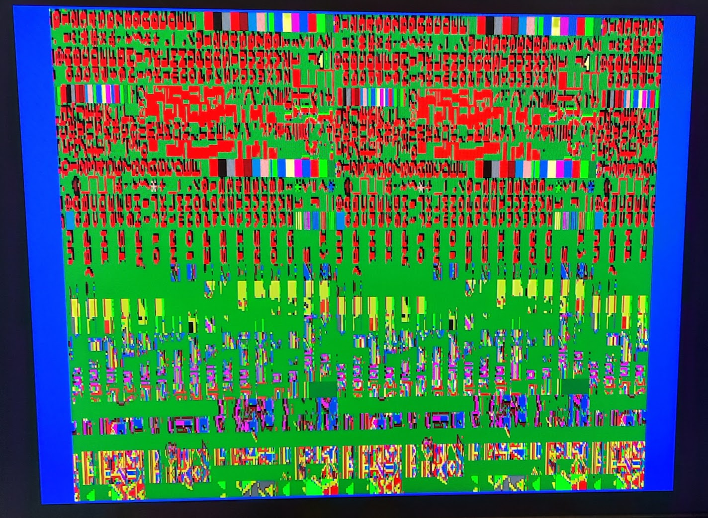
Once that looked OK, I did the same for the vertical timing. When vertical looked OK, I did a quick hack to output the border in RED, and the active display area in GREEN. Here is where I had to make some changes to the Verilator template project to handle YGV608 video output (as opposed to Centipede video output). But it wasn't too long before I saw this...

YGV608 Video Timing output in Verilator

Next step was to build for MiSTer. Because I had changed the top-level of my core, I had to do some minor changes to the wrapper that instantiates my core but otherwise there were no changes required for the MiSTer project, except to change the parameters for the main PLL to output the correct frequency for the YGV608.

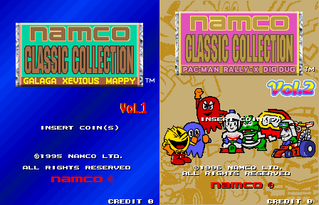
And this is what I saw when I ran it from the MiSTer menu for the very first time...

YGV608 Video Timing output on MiSTer hardware

Yes the borders are different but the Verilator video output is (still) a bit of a hack from my side of things and I haven't yet taken the time to fully understand the video output configuration properly. The point is, I think the MiSTer borders are correct!

So that has been a very successful first exercise in getting something simulated and then running on MiSTer hardware! I'm very impressed with Verilator and JimmyStone's framework. There are some limitations - for example it can't handle SystemVerilog aliases - but the productivity gains are astronomical.

So what's next? I need to load the YGV608 graphics ROMs into the Verilator project. They're loaded into MiSTer SDRAM via the framework, and there's a similar mechanism in the Verilator template project. However there's (currently) no emulation of the SDRAM so you need to instantiate some memory in the top-level Verilog wrapper to store the downloaded data and essentially replace the SDRAM. I've added the ROM file to the Verilator project, and can see it downloading on gtkwave, so now all I need to do (in theory) is instantiate some simple DPRAM for the simulation.

Once that's done I can quickly hack the YGV608 core to simply dump (some of) the ROM contents to the active display area...

Friday 24 November 2023

Resurrection!

After some 7 years I'm back!

I've renamed the blog (and the URL) and given the untimely demise of my NGPACE project, I've revised the topic to comprise all my retro FPGA emulation projects.

After a very long hiatus from homebrew FPGA development, I've decided to put porting on hold for a while and dive back into FPGA emulation. More specifically, development for the MiSTer platform.

There's a pretty big ramp-up to develop for MiSTer, but the simulation tools available now are simply amazing. I'll do a brief intro to both MiSTer and the simulation options in subsequent posts.

I'll leave you with a screenshot of my first project. 


It will be more complex than any FPGA emulation projects I've done in the past, but I've been motivated by recent developments in PSX, Saturn & N64 FPGA emulation which are truly incredible!